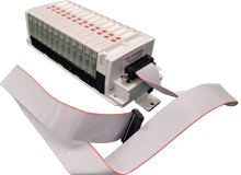
Producer Gas Box Pneumatic Manifold Replacement
Valin has engineered a drop-in pneumatic manifold replacement that is a perfect solution for your obsolete Producer gas box pneumatic manifold on your aging fleet of Producer process tools.
Watch Video
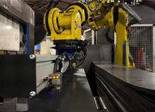
Valin Supporting an Automated Press Brake Work Cell with Flexible Conveyance and Safety Infrastructure
See how Valin helped support an advanced automated press brake work cell with a flexible, safety-focused solution designed to improve productivity and protect operators.
Watch Video
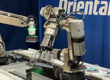
Oriental Motor Built a Robot and Conveyor Automation Demo
Submitted by Oriental Motor
Oriental Motor built a robot and conveyor automation demo to showcase a revolving robotic pick-and-place process, a common method used to perform warehouse automation tasks, such as picking, packing, shipping, receiving, unpacking, and stocking.
Watch Video
How To Setup a Beijer X2 Pro HMI with a CODESYS PLC
Submitted by Tom Trinh || Valin Corporation
This video will illustrate how to set up a Beijer HMI X2 Pro 10 to communicate with a CODESYS PLC using the CODESYS driver.
Watch Video
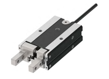
How to Install The EC Series Wire Grippers Wire
Get your EC Series Wire Gripper installation just right with this clear, step-by-step tutorial!
Watch Video
How to Install The EC Series Wire Rods Wire
Begin your professional installation with confidence! In this detailed tutorial, we walk you through each step of installing the control wires in the EC Series Wire Rod actuator (EC-WER type) from IAI
Watch Video
How to Set Up Communication Between a Mitsubishi PLC and an IAI RCON Gateway Controller
Submitted by Tom Trinh || Valin Corporation
In this step-by-step tutorial, Tom Trinh, Senior Application Engineer at Valin Corporation, walks you through the complete process of setting up communications between a Mitsubishi PLC and an IAI RCON Gateway Controller using the CC-Link Field Network.
Watch Video
How to Setup the IAI RCON Gateway for CC-Link Field Network Using IAI IA-OS Software
Submitted by Tom Trinh || Valin Corporation
Join Tom Trinh as he walks you through the process of setting up an IAI RCON Gateway with a CC-Link field network using the IAI IA-OS configuration software.
Watch Video
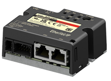
How To Setup Oriental Motor's AZD-KREP with a PLC Using Ethernet IP
Submitted by Tom Trinh || Valin Corporation
In this comprehensive tutorial, Tom Trinh, Senior Application Engineer at Valin Corporation, walks you through the complete setup of the Oriental Motor AZD-KREP driver using Ethernet/IP.
Watch Video
Why Yokogawa e-RT3 for Affordable Machine Vision
Submitted by Levi Transtrum || Valin Corporation
In this video, Levi demos the Yokogawa e-RT3 PLC.
Watch Video
Dual Carriage XXYYZZ Pick and Place Stage
This 6-axis precision pick and place stage system by PBA Systems was engineered from the ground up and delivered in 10 weeks. This high-performance stage system was designed to optimize throughput, size and cost, without sacrificing positioning performance.
Watch Video
Parker's XLM Series Linear Motor Stages
For machinery or instrument builders who need smooth motion and high precision, Parker offers the XLM series. The XLM is a linear positioner that provides micron level precision in three different profile widths from 125mm to 200 mm. Its modular design allows for easy assembly of multi-axis systems.
Watch Video
How To Set Up Autonics BD-100R Using ATDisplacement Software
Submitted by Tom Trinh || Valin Corporation
The video provides a detailed guide on setting up the Autonics BD-100R laser measurement sensor using the ATDisplacement software. Tom Trinh, Senior Application Engineer at Valin Corporation, demonstrates the setup process.
Watch Video
How to Communicate to an IAI RCON Controller Using Modbus TCP
Submitted by Tom Trinh || Valin Corporation
This video will illustrate how to send a Modbus TCP command to an IAI RCON with the Ethernet option - ET. That allows you to control the RCP6 actuators, to turn on the servo on, and to home the actuators, as well as commanding the actuators to go to a certain position with the specified velocity, acceleration, deceleration, and so forth.
Watch Video
How to Setup the Oriental Motor AZD-KED Drive to Work with a PLC that has an EtherCAT Master
Submitted by Tom Trinh || Valin Corporation
Tom Trinh, a Senior Application Engineer at Valin Corporation, provides a detailed explanation on how to connect an Oriental Motor EtherCAT drive (model AZD-KED) to a PLC. The demonstration uses an Omron NX series PLC, but the process is applicable to any PLC supporting EtherCAT, such as Allen Bradley, Siemens, and Mitsubishi.
Watch Video
Acromag DT Series Programmable Dual Channel Transmitters
Introducing Acromag's new DT Series. These Programmable Dual Channel Transmitters have two independent signal conditioners in one module, saving you money and saving you space at only 17.5 mm wide.
Watch Video
How to Set Up Remote IO Over Modbus TCP on Mitsubishi FX5
Submitted by Levi Transtrum || Valin Corporation
This video illustrates how to setup a remote IO on a Mitsubishi FX5U over Modbus TCP.
Watch Video
How to Control a Mitsubishi E-800 Inverter over CC-Link IE Field Basic Network
Submitted by Levi Transtrum || Valin Corporation
This video will demonstrate how to setup a Mitsubishi FX5U CPU to control a Mitsubishi E-800 Inverter.
Watch Video
How To Communicate to the Parker P-Drive Using a Modbus RTU
Submitted by Tom Trinh || Valin Corporation
This video will illustrate how to communicate to the P drive from Parker using Modbus RTU and you can send a command down to turn on the servo, to home it as well as jog it, and also execute the index whatever the position you want the motor to go and everything once again using Modbus RTU and the RS422 cable.
Watch Video
How To Setup a Modbus RTU Command to Control an IAI RCP6-RRA Pulse Press
Submitted by Tom Trinh || Valin Corporation
This video will illustrate how to send Modbus RTU command to an IAI PCON controller to control the actuator.
Watch Video
How To Setup the IAI RCP6 RRA Pulse Press
Submitted by Tom Trinh || Valin Corporation
This video will illustrate how to set up an IAI RCP6-RRA pulse press.
Watch Video
Patlite's USB Controlled LED Signal Tower LR6-USB
Patlite's USB controlled signal tower can be used immediately because it has USB bus power and does not require a dedicated driver.
Watch Video
Patlite IO-Lin LR6-IL and NE-IL
Patlite's IO-link devices have many advantages, among them are they are controllable via IO-link, are easy to install, have seven selectable colors in various alarms, non IO-link sensors are supported , and they are highly visible so you can quickly understand operating instructions and status.
Watch Video
Patlite LA6-POE Ethernet Programmable LED Signal Tower
You have endless possibilities with Patlite's Ethernet Programmable LED Signal Tower. Get power over ethernet, easy connection and communication with one cable, and easily control and receive feedback with various commands.
Watch Video