Q: What are the biggest challenges you see today when it comes to control valve sizing?
A: The biggest challenge is to get accurate process data. It is quite common for someone other than the person who designs the system to do the control valve sizing. When I worked at a large engineering company, the process engineer would determine the absolute maximum flow that would ever be required and then he would send his requirements to the mechanical engineers (who were in a different building). The mechanical engineers would select a pump after applying what they felt was a sufficient safety factor and forward the flow requirements to the control system engineers (also in another building). The control system engineers would add their own safety factors. As a result, a lot of valves were oversized.
There is nothing wrong with including adequate safety factors, but everyone involved needs to communicate. The person sizing a control valve needs to at least know the minimum and maximum required flow rates, along with the corresponding values of P1 (pressure upstream of the valve) and P2 (pressure downstream of the valve). These pressures should be determined from a hydraulic analysis of the system at each flow rate. It is also very helpful to have similar data for the normal flow rate.
Q: What do you see as some of the main trends or advances to come in valve selection and sizing?
A: Recently, I have seen that some valve manufacturers have an online control valve sizing program. One major control valve manufacturer programmed the front end of its full-featured valve sizing and selection software in Java so that they could easily port it to an online application, though they haven't taken this last step so far. The reason for making an online application is so that users would not have to download and install anything, and they would always be assured of using the latest version.
Something that has been talked about in the last few years is the benefit of being able to do an installed gain analysis of several valve types or sizes in a particular application, as an aid in selecting the valve that will do the best job of controlling the process. To my knowledge, there are only two control valve manufacturers who claim to have software that can analyze the installed gain, one of which makes this capability available for its customers to use. I think in the future, due to popular demand, more control valve manufacturers will include this feature in the software that they provide to their customers.
Another trend that I have seen in control valve selection is that as users are becoming more interested in finding control valve solutions that are more economical and have higher control rangeability, they are looking at rotary control valves more often today than they have in the past.
Q: Are there "rules of thumb" that can be applied for selecting the correct inherent flow characteristic for a particular application and selecting the correct control valve size?
A: Yes, rules of thumb do apply and a valve that meets the rules of thumb below is usually the best choice:
If a system has a lot of pipes (most common), use an equal percentage valve.
- If the system has very little pipe, use a liner valve.
- If a set of loop tuning parameters only works at one end of the control range and not the other, the valve's flow characteristic is most likely the wrong one.
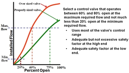
- A control valve that is sized to operate around 60 percent to 80 percent open at the maximum required flow and not much less than 20 percent open at the minimum required flow will give the best control.
- Properly sized full ball, segment ball, and high-performance butterfly valves are usually two sizes smaller than the line.
- Properly sized globe valves are usually one size smaller than the line.
- Oversized control valves are very common.
A popular "rule of thumb" for selecting a properly sized control valve.
Q: Considering the nature of the flow of liquids through control valves, what are some methods for eliminating cavitation damage? And how can you predict the potential for cavitation damage?
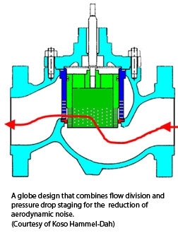
A: Methods of eliminating cavitation damage include both valve style selection and process modifications. Special valve designs for eliminating cavitation employ flow division and pressure drop staging, sometimes individually and sometimes together. 'Flow division' divides one large flow into several smaller flows by designing the flow path in the valve so that the flow passes through several small parallel openings. This is effective because the size of the cavitation bubbles is partly a function of the size of the opening the flow is traveling through. Smaller openings make smaller bubbles, which results in less noise and less damage when they collapse.
"Pressure drop staging" means that the valve is designed to have two or more throttling points in series so that instead of taking the entire pressure drop in a single step, it is taken in several smaller steps. Smaller individual pressure drops can prevent the pressure at the vena contracta (the point where the velocity is the highest and the local pressure is the lowest) from dropping to the liquid's vapor pressure, thus eliminating cavitation. Improved cavitation resistance can be obtained by combining flow division and pressure drop staging in the same valve.
Modifying the process to locate the control valve where the pressure at the valve inlet is higher (such as farther upstream or at a lower elevation) can sometimes eliminate a cavitation problem. Also, locating the control valve at a location where the liquid temperature, and thus the vapor pressure, is lower (such as the low-temperature side of a heat exchanger) can help eliminate a cavitation problem.
Predicting cavitation damage is not as simple as calculating the choked flow pressure drop. Experience has shown that there are likely to be areas of localized vaporization and vapor bubble collapse before the pressure in the main flow stream drops to the vapor pressure of the liquid. Some valve manufacturers predict the beginning of cavitation damage by defining an incipient damage pressure drop. One valve manufacturer's method of predicting the beginning of cavitation damage is based on the fact that it is vapor bubble collapse that causes both cavitation damage and noise. This manufacturer has determined that if calculated noise levels are below the following limits, significant cavitation damage will be avoided.
- Up to 3-inch valve size 80 dBA
- 46-inch valve size 85 dBA
- 814-inch valve size 90 dBA
- 16-inch and larger valve size 95 dBA*
*These parameters were established in a study by Neles/Metso.
Q:What valve designs should be considered for reducing excess aerodynamic noise?
A: There are two strategies for reducing aerodynamic noise—source control and path control. Source control is implemented through flow division and/or pressure drop staging (mentioned in the previous answer), which basically does something to the valve to make it less noisy. When pressure drop is taken in more than one step, the individual velocity peaks are smaller than the velocity peak that would result from a single-stage pressure drop. Since aerodynamic noise is strongly related to velocity, small reductions in velocity can have a large effect on reducing the noise. When the gas flow is divided into several smaller parallel flows, the frequency of the noise generated is shifted to a higher frequency, which is attenuated to a greater degree as it passes through the pipe wall to where the people are. Also, people's hearing (and noise meters calibrated for dBA) are less sensitive to higher frequencies.
Path control is simply doing something to the space between the noise source and the people who would be bothered by it. It can be effective for aerodynamic noise but is of limited value for hydrodynamic noise because high hydrodynamic noise usually indicates damaging levels of cavitation, which must be dealt with at the source.
There are three-path control methods worth mentioning:
- Distance
- Heavy wall pipe
- Thermal or acoustic insulation
Q: What are the symptoms used to diagnose excessive stiction? And what criteria do you recommend for control valve performance?
A: The test for stiction and dead band consists of a series of small steps of control signal to the valve, first in one direction, then in the reverse direction. Stiction is the sticky behavior of valves and the result of interaction between static friction (high) and dynamic friction (low). If you push lightly on a valve stem, nothing happens. If you push a little harder, still nothing happens. Finally, when you push hard enough to overcome the static friction the valve moves fairly fast because the dynamic friction is lower. Excessive stiction in a closed-loop system results in a limit cycle and process variability.
Control valve performance has a major impact on the valve's contribution to process variability. The most important measures of valve performance are resolution (stiction), dead band, and speed of response. Below are some guidelines for valves in processes where very good control is required:
- Resolution (stiction): < 0.5 percent
- Dead band: < 0.5 percent
- Speed of response:
- Fast loops: Valve Td < 20 percent of desired closed-loop process time constant; Valve T86 < 40 percent of desired closed-loop process time constant (This is equivalent to saying that the valve should be five times faster than the desired closed-loop process response time.); Valve settling time < desired closed-loop process time constant. - Slow loops: not important
- Step overshoot: A maximum of 20 percent of step size
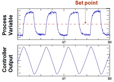
Process Variable and Controller Output
Process Variable and Controller Output
Excessive stiction in a closed-loop system results in a limit cycle
Q: What are the benefits of using an installed gain analysis to select a control valve that will be able to control well in a particular system?
A: Using installed gain analysis will help you determine if the gain is too low or too high. If the gain is too low, when the valve moves the flow hardly changes, which means the valve will not be effective in controlling flow. If the gain is too high, small errors in valve position will result in large errors in flow, making it difficult or impossible to control accurately.
Typically, if the gain changes by not much more than a 2-to-1 ratio, it will be possible to come up with one set of PID tuning parameters that will result in good control and stability throughout the required flow range. The more constant the gain, the more aggressive the PID tuning can be without the danger of instability.
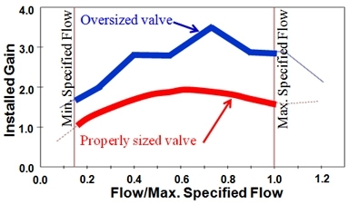
Installed Gain vs Flow Max
Installed Gain vs Flow Max
An installed gain analysis of two control valves shows that the properly sized valve has
1) less gain variation within the specified flow range than the oversized valve, permitting more aggressive PID tuning; and
2) a lower average gain resulting in smaller flow errors for the same amount of position error.
Click here to download this article in PDF format PDF_SMALL
Click here to view this article on Flow Control's website.
Jon Monsen, Ph.D., P.E. is a control valve technology specialist at Valin Corporation. His focus is on providing technical training and assisting Valin's customers in the proper application of control valves.