
Resources
Determining the Pressure Drop to be Used in a Control Valve Sizing Calculation
Submitted by Jon Monsen, PhD
Perhaps the most misunderstood area of control valve sizing is the selection of the pressure drop, Δp, to use in the sizing calculation. The Δp cannot be arbitrarily specified without regard for the actual system into which the valve will be installed. What must be kept in mind is that all of the components of the system except for the control valve (pipe, fittings, isolation valves, heat exchangers, etc.) are fixed and at the flow rate required by the system (to cool a hot chemical to a specified temperature, maintain a specified level in a tank, etc.) the pressure loss in each of these fixed elements is also fixed. Only the control valve is variable and it is connected to an automatic control system. The control system will adjust the control valve to whatever position is necessary to establish the required flow (and thus achieve the specified temperature, tank level or whatever). At this point the portion of the overall system pressure differential (the difference between the pressure at the beginning of the system and at the end of the system) that is not being consumed by the fixed elements must appear across the control valve.
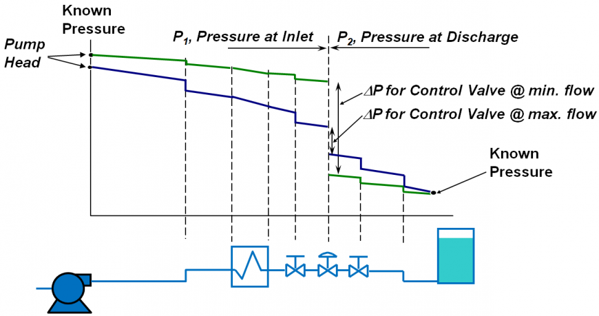
Assuming that you need to size a control valve for a system that has been designed, but not yet built, or perhaps a system that is running, but it is not possible, or convenient, to get reliable pressure measurements near the control valve, the correct procedure for determining the pressure drop across a control valve at the flow rate for which you plan to perform a sizing calculation, is as follows: Start upstream of the valve at a point where the pressure is known (for example a pump where the pressure can be determined from the head curve) and subtract the pressure loss in each of the fixed elements. When you get to the valve inlet you know p1, the pressure immediately upstream of the valve. At this point you cannot directly calculate the pressure drop across the valve, because you have yet to determine both its size and the percentage of opening at which it will be operating. The next step is to go to a point downstream of the control valve where the pressure is known (for example, a tank where the head is known) and then work upstream toward the control valve, adding the pressure loss of each of the fixed elements. (You are adding the pressure losses because you are working in the direction opposite to the flow.) When you get to the valve outlet you know p2, the pressure immediately downstream of the valve. The actual pressure drop across the control valve is the difference between the upstream and the downstream pressures, that is Δp = p1 - p2. If you plan to perform sizing calculations at more than one flow rate (for example, at both maximum and minimum design flows) you must repeat the calculation of p1 and p2 at each flow rate, since the system pressure losses (and pump head) are dependent on flow. With realistic pressure drop data, determined as above, along with your other process data, we can use state-of-the-art control valve sizing software to size your control valve correctly for the application to insure optimal control while reducing noise and valve wear.
Jon Monsen, Ph.D., P.E. is a Control Valve Technology Specialist at Valin Corporation.
Other white papers that may be of interest:
Pressure at the Vena Contracta with Liquid Flow in a Control Valve
Installed Gain as a Control Valve Sizing Criterion
Aerodynamic Noise in Control Valves
Valve Aerodynamic Noise Reduction Strategies
Size Matters: Control Valve Sizing 101
The content of these white papers are just a small portion of what you will learn in Dr. Monsen's book: Control Valve Application Technology
Would you rather learn from Dr. Monsen directly and have the ability to ask him questions? Take one or more of his webinars:
- Control Valve Overview
- Effect of Control Valve Sizing and Flow Characteristic on Controllability
- Liquid Flow in Control Valves
- Gas Flow and Aerodynamic Noise in Control Valves
- Control Valves and Process Variability
- Installed Gain as a Control Valve Selection Criterion

A lesson for me is that I need to involve you earlier in the program.
You were tireless in your support and it will not be forgotten!