
Resources
Pressure at the Vena Contracta with Liquid Flow in a Control Valve
Submitted by Jon Monsen
I was recently asked how the pressure at the vena contracta of a control valve in a liquid application can be determined. I am sharing my answer below.
Here are some comments on the pressure at the vena contracta:
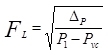
The Liquid Pressure Recovery Factor, published by control valve manufacturers for each of their valves, is defined as:
Here are some comments on the pressure at the vena contracta:
The Liquid Pressure Recovery Factor, published by control valve manufacturers for each of their valves, is defined as:
Where:
ΔP is the pressure drop across the valve (P1 – P2)
P1 is the absolute pressure upstream of the valve.
PVC is the pressure at the vena contracta.
It is important to understand that this equation is only valid when the density at the vena cotracta remains constant. It does not apply when there is vaporization at the vena contracta.
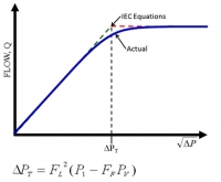
The valve manufacturers determine the FL of their valves by increasing the pressure drop across the valve until flow becomes fully choked.
The flow vs. square root of pressure drop actually follow the blue line on the figure below, but the IEC liquid valve sizing equations don't attempt to predict the rounded portion of the graph, but instead predict a flow vs. square root of pressure drop relationship as shown by the green and red dashed lines.
Once the test determines that flow is fully choked (the flow does not increase with increasing pressure drop), the point where the red and green lines on the figure intersect is defined as the transition point between non-choked flow and choked flow and is also the point that separates the IEC equation for liquid non-choked flow from the IEC liquid equation for choked flow. The IEC does not give this point a name. I like to call it the "Terminal Pressure Drop," abbreviated ΔPT . Others have called it various things, such as "Allowable pressure drop" "Critical pressure drop" and "Max pressure drop," to mention a few.
The valve manufacturer then solves the IEC equation for the Choked flow point (what I call ΔPT ) to come up with FL.
Where PV is the vapor pressure of the liquid
and FF is the "Critical Pressure Ratio factor"
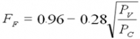
Where PC is the thermodynamic critical pressure of the liquid.
Back to the question of determining the pressure at the vena contracta, you can rewrite the equation that defines FL in terms of the pressure at the vena contracta, PVC
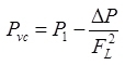 This is only valid up to the point where choked flow begins. Once flow becomes choked there is vaporization at the vena contracta and the density at the vena contracta decreases. When the density decreases, the pressure recovery decreases. Once vaporization at the vena contracta is fully developed, the pressure at the vena contracta reaches its lower limit. If the downstream pressure is then further decreased, the result will be more vaporization, but the vena contracta pressure is not affected and the flow rate stays the same.
Most of the polished information i have seen on choked flow and cavitation is based on tests with cold water. I have no experience with or knowledge of the effects of solutions and mixtures of liquids, such as hydrocarbon liquids.
Other white papers that may be of interest:
Installed Gain as a Control Valve Sizing Criterion
Aerodynamic Noise in Control Valves
Valve Aerodynamic Noise Reduction Strategies
Determining the Pressure Drop to be Used in a Control Valve Sizing Calculation
Size Matters: Control Valve Sizing 101
The content of these white papers are just a small portion of what you will learn in Dr. Monsen's book: Control Valve Application Technology
Would you rather learn from Dr. Monsen directly and have the ability to ask him questions? Take one or more of his webinars:

ΔP is the pressure drop across the valve (P1 – P2)
P1 is the absolute pressure upstream of the valve.
PVC is the pressure at the vena contracta.
It is important to understand that this equation is only valid when the density at the vena cotracta remains constant. It does not apply when there is vaporization at the vena contracta.
The valve manufacturers determine the FL of their valves by increasing the pressure drop across the valve until flow becomes fully choked.
The flow vs. square root of pressure drop actually follow the blue line on the figure below, but the IEC liquid valve sizing equations don't attempt to predict the rounded portion of the graph, but instead predict a flow vs. square root of pressure drop relationship as shown by the green and red dashed lines.
Once the test determines that flow is fully choked (the flow does not increase with increasing pressure drop), the point where the red and green lines on the figure intersect is defined as the transition point between non-choked flow and choked flow and is also the point that separates the IEC equation for liquid non-choked flow from the IEC liquid equation for choked flow. The IEC does not give this point a name. I like to call it the "Terminal Pressure Drop," abbreviated ΔPT . Others have called it various things, such as "Allowable pressure drop" "Critical pressure drop" and "Max pressure drop," to mention a few.
The valve manufacturer then solves the IEC equation for the Choked flow point (what I call ΔPT ) to come up with FL.
Where PV is the vapor pressure of the liquid
and FF is the "Critical Pressure Ratio factor"
Where PC is the thermodynamic critical pressure of the liquid.
Back to the question of determining the pressure at the vena contracta, you can rewrite the equation that defines FL in terms of the pressure at the vena contracta, PVC
Most of the polished information i have seen on choked flow and cavitation is based on tests with cold water. I have no experience with or knowledge of the effects of solutions and mixtures of liquids, such as hydrocarbon liquids.
Other white papers that may be of interest:
Installed Gain as a Control Valve Sizing Criterion
Aerodynamic Noise in Control Valves
Valve Aerodynamic Noise Reduction Strategies
Determining the Pressure Drop to be Used in a Control Valve Sizing Calculation
Size Matters: Control Valve Sizing 101
The content of these white papers are just a small portion of what you will learn in Dr. Monsen's book: Control Valve Application Technology
Would you rather learn from Dr. Monsen directly and have the ability to ask him questions? Take one or more of his webinars:
- Control Valve Overview
- Effect of Control Valve Sizing and Flow Characteristic on Controllability
- Liquid Flow in Control Valves
- Gas Flow and Aerodynamic Noise in Control Valves
- Control Valves and Process Variability
- Installed Gain as a Control Valve Selection Criterion
A lesson for me is that I need to involve you earlier in the program.
You were tireless in your support and it will not be forgotten!