Input Filters
The use of Input filters are to reduce the erratic fluctuations of the analog input signal due to either electrical "noise" conditions or rapid fluctuations of the analog input signal. It accomplishes this by slowing down the response of the analog input to a change.
AC noise levels can be from either lack of AC grounding problems or intermittent RFI from opening of contacts of control relays of the system.
The filtering of the input can reduce these levels to avoid unnecessary changes in the controller output signal levels.
The filter works by providing a time period over which the amount of the analog input increasing or decreasing change is allowed to change. The filter value of time is the amount of time that 66.6% of the change in the input level will be "seen" by the controller. It takes three time periods to "see" 96.3% of the total change in the analog input level. It takes five time periods to "see" 99.6% of the total change level.
The most common input response time for TC analog inputs is three seconds. The range can be as fast as 0.2 second to 42 seconds for the CLS204 or as slow as 1.3 second to 340 seconds with the MLS332 controller.
A starting value for the input filter can be obtained by dividing the TI value by 30. This is only an initial start value and may be changed.
Output Filters
Output filters are used to provide filtering of the control output level. The use of the Derivative Mode may be a cause of the stability of the output level. The output filter can be used to remove this erratic change due to the Derivative mode.
Divide the TD value by 3 to use the output filter to remove effects of using the D mode in the controller PID function.
Output filters are also used to reduce the change in the output level due to process dynamics. The use of very fast response control elements such as radiant heaters or flow processes or exposed tip TC sensors in forced air processes can use output filtering as well. Suggest using a 5 to 25 seconds filter value.
The Watlow PPC-2000 does not require extra filtering to have an effective D Mode.
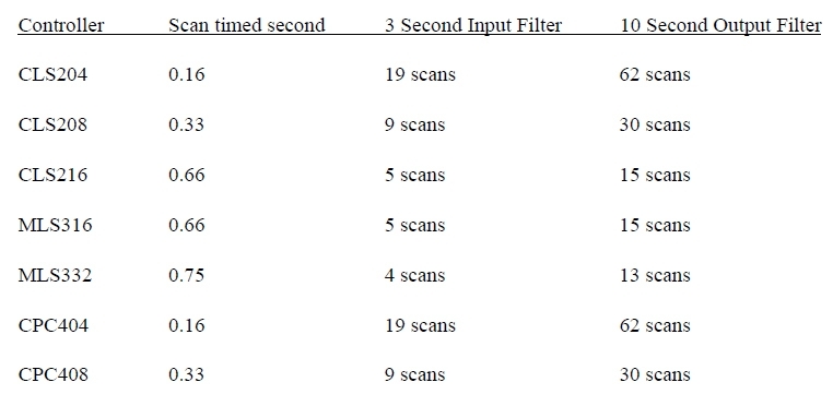
Filter Scan Times
The INPUT Filter and OUTPUT Filter are set to factory default values of 3 scans. This is not the value of time in seconds, rather the number of scans per second. The number of scans per second is determined by the controller scan time rate. The number of channels of the controller determines the scan time period. Divide the time period required by the scan time period of the controller to get the scan value required for the filter setting.
Image
Download White Paper