How Does an RTD Work?

Ashcroft

Resistance temperature detectors (RTDs) are passive components whose resistance changes with a change in temperature. This can be measured very accurately, enabling an RTD to translate temperature into a stable electrical signal, even in demanding industrial environments.

As a trusted resource in pressure and temperature measurement, Ashcroft helps users understand how RTDs function so they can select the right sensing technology for their process.

In this article, you’ll learn how an RTD senses temperature, how the materials and construction of the sensing element influence accuracy, why wiring configuration matters and how these factors help determine which RTD design is best suited for your application.


What is an RTD's electrical resistance?

Electrical resistance is the opposition to the flow of the electrical current. RTD temperature sensors rely on the relationship of resistance to temperature. For example, as the temperature rises, the resistance of the RTD element increases; and as the temperature decreases, the resistance decreases.

The reliability of this resistance response is influenced by two key factors: the metals used in the sensing element and the way the RTD is built and wired into the circuit. The sensing element material determines how stable, repeatable and accurate the resistance change will be.

Materials that help maintain accuracy 
Material choice directly influences how well the RTD maintains accuracy across different operating conditions.

1.Platinum 100 ohm
Pt100 RTD sensors are passive components and require an excitation current to produce an output signal. This is the preferred RTD element material because it offers:

  • Excellent corrosion resistance
  • Proven long-term stability
  • A wide range of temperature, from -200 to +850 °C.

These characteristics make platinum suitable for processes requiring accuracy over time, including cryogenic systems where temperatures can reach –196 °C.

2. Nickel and Copper.
These materials are less common than platinum options and have limited temperature ranges.

  • Nickel offers good corrosion resistance, but ages more quickly and loses accuracy at higher temperatures. This material is usable in applications with temperature ranges from –80 to +260 °C.
  • Copper offers the best resistance to temperature linearity of the three RTD types. However, it oxidizes at higher temperature. It is usable in applications with temperature ranges from –200 to +260 °C.
     

How does RTD element construction impact on performance?

Instrument accuracy, linearity and usable temperature range are all affected by whether the RTDs sensing element is a wire-round or thin film construction. Each is rated based on its resistance at 0°C.

Wire-Wound RTDs
This type of RTD is ideal for applications requiring precision under extreme temperature conditions. They are made from a fine platinum wire coil that provides excellent accuracy and long-term stability, and supports the broadest operating range from –200 to +850 °C.

Thin-Film RTDs
Thin-film RTDs are often selected for less extreme temperature ranges. They use a platinum layer deposited on a ceramic substrate, are compact and fast to respond. These RTDs typical have an operating range of –50 to +400 °C. 

Figure 1: Wire round vs. thin film construction


What are the effects of lead wire and wiring configurations?

Because an RTD measures resistance, any resistance introduced by lead wires influences accuracy. Wiring configuration therefore is essential to how accurately the RTD performs once installed.

Typical lead-wire options on for an RTD:

2-wire RTD
The 2-wire RTD configuration is the simplest among RTD circuit designs. A single lead wire connects each end of the RTD element to the monitoring device. The total circuit resistance includes the lead wire resistance. This is the least accurate of the configurations and used for applications with short lead lengths.

Figure 2: 2-Wire RTD


3-wire RTD
The 3-wire RTD configuration is the most common RTD circuit design used in industrial processes. In this setup, two lead wires are connected to one side of the sensing element and a single lead wire is connected to the other side. By allowing the monitoring device to compare the resistance of the paired leads, this configuration effectively compensates for the lead wire resistance on one side of the element, significantly improving overall measurement accuracy.

Figure 3: 3-Wire RTD

4-wire RTD
The 4-wire RTD configuration is the most complex and typically the most expensive, but it provides the highest level of measurement accuracy. In this design, two pairs of lead wires connect to the sensing element, allowing the monitoring device to fully cancel out the lead wire resistance on both sides of the circuit.

Figure 4: 4-Wire RTD


Why do accuracy classes matter?

Accuracy classes identify how closely an RTD element matches the ideal resistance-temperature curve defined by IEC 60751. Common accuracy classes include:

  • Class B: ±0.3 °C (widest operating range)
  • Class A: ±0.15 °C
  • Class AA: ±0.1 °C (tightest tolerance)
     

Where RTDs are commonly used?

RTDs are widely used in industries that rely on accurate, stable temperature measurements, including:

  • Oil and gas industries
  • Power plants
  • Chemical and refining processes
  • Pharmaceutical and biotechnology systems
  • Cryogenic storage and low-temperature production
  • Compressor and turbine monitoring
  • Safety shutdown systems and critical control loops


Talk to one of our experts today at (855) 737-4715 or fill out our online form to learn more.

What's the Difference Between NIST and ISO/IEC 17025 Calibration?

Ashcroft

The National Institute of Standards and Technology (NIST) is the U.S. National Metrology Institute responsible for maintaining primary measurement standards. ISO/IEC 17025 is the internationally recognized standard for testing and calibration laboratories. Both organizations provide widely recognized calibration frameworks used to ensure accurate, reliable measurement results across many industries.

Although these terms are often associated with pressure instruments, both NIST traceability and ISO/IEC 17025 accreditation apply to the calibration laboratories performing the work, not to the instruments themselves.

Selecting which calibration testing method is needed for pressure measurement depends on how the instrument will be used. As a trusted authority in pressure and temperature measurement, Ashcroft frequently guides customers who are seeking clarity on calibration standards, documentation requirements and best practices for testing and maintaining measurement accuracy.

Read this article to learn how NIST traceable and ISO/IEC 17025 accredited calibrations differ, what each certification means and how to determine the right level of calibration for your application.
 

What Is a NIST Traceable Calibration?

A NIST traceable calibration is a more cost-effective method that ensures the calibration standard is traceable to the U.S. National Measurement Institute. A NIST traceable calibration verifies:

  • Reference standards used during calibration can be traced back to NIST through an unbroken chain of comparisons. This confirms your instrument aligns with U.S. national measurement standards, providing a reliable baseline for industrial measurements.
  • Calibration documentation showing the traceability chain. This allows users to verify exactly how measurements were established, helping support internal quality processes and audits.
  • Consistency with national measurement standards. This verifies pressure readings remain uniform across different locations or equipment using NIST-traceable references.
     

What a NIST traceable calibration does not include, and why it matters

  • No assessment of laboratory competence. This provides faster and more affordable calibration services for applications that don’t require full lab accreditation.
  • No validated method review. This is suitable for general-purpose or non-regulated processes where method verification is not required.
  • No environmental condition verification. Helps streamline calibration for routine industrial measurements where control of temperature or vibration is not critical.
  • No measurement uncertainty requirement. Provides fewer documentation requirements, which is ideal when uncertainty values are not required by the quality system.
     

NIST traceable calibration key Benefits:

  • Cost-effective calibration suitable for most industrial applications
  • Faster turnaround times
  • Supports routine monitoring and general process control
  • Provides adequate accuracy for non-critical measurements
     

What Is ISO/IEC 17025 Accreditation Calibration?

ISO/IEC 17025 is the international standard that evaluates the competence of the entire calibration laboratory and documents measurement uncertainty. This standard was developed and published jointly by the International Organization for Standardization (ISO) and the International Electrotechnical Commission (IEC) to provide global guidelines for laboratory quality and technical data.

ISO/IEC 17025 evaluates more than the reference standard used during calibration. It also focuses on the entire calibration system, including:

  • Traceability to national or international standards. Ensures every measurement connects to recognized metrology institutes, improving confidence and global consistency.
  • Defined and documented measurement uncertainty. Gives a clear understanding of the precision of each measurement, helping you evaluate risk and meet regulatory or validation requirements.
  • Competence and training of personnel. Reduces the likelihood of human error by ensuring calibrations are performed by qualified, regularly evaluated technicians.
  • Validated calibration methods. Demonstrates that calibration procedures are tested, repeatable and proven reliable, strengthening confidence in results.
  • Environmental controls (temperature, vibration, humidity). Prevents outside conditions from influencing calibration readings, improving stability and repeatability.
  • The quality management system. Ensures proper documentation, corrective actions and process controls are in place, which is important for audits and long-term reliability.
  • Regular audits by independent accreditation bodies. Provides ongoing, third-party verification that the laboratory continues to meet ISO/IEC 17025 standards over time.
  • Accreditation from ANAB or other ILAC-recognized bodies. Ensures calibration results are accepted internationally, reducing duplicate testing and simplifying compliance across borders.
     

ISO/IEC 17025 Key Benefits:

  • High level of confidence in measurement accuracy
  • Accepted internationally without the need for retesting
  • Comprehensive documentation for regulatory audits
  • Detailed uncertainty reporting
     
Figure 1: ISO/IEC 17025 and a NIST Traceable Calibration Comparison Chart


Which calibration method do I choose?

Choosing the right calibration standard depends on your application’s risk level, regulatory oversight and accuracy requirements.

Figure 2. Which method to choose?


Examples of instruments commonly used in calibration work 

Reference instruments play an important role in both ISO/IEC 17025 and NIST traceable calibrations. For instance, test gauges and handheld calibrators serve as comparative tools during calibration or verification routines.

The following are examples of Ashcroft instruments that can be calibrated to either ISO/IEC 17025 or NIST standard, depending on what the user requests from the calibration lab.

The Ashcroft®1082 Test Gauge is an ASME Grade 3A reference gauge that provides accuracy to ±0.25% of span. Its mirror-band dial and knife-edge pointer help eliminate parallax error, which is an important factor when performing high-precision comparisons.

The Ashcroft®1084 Test Gauge is a compact test gauge with ±0.5% of span. It is used for field verification of installed pressure devices and includes a protective carry pouch, making it convenient for technicians performing on-site NIST traceability checks.

The Ashcroft® ATE-2 Handheld Calibrator is a digital, multi-function instrument that can measure pressure, temperature, voltage and current, and offers accuracies down to ±0.025% of span depending on the pressure module. It is used for documenting calibration points during field work.


Talk to one of our experts today at (855) 737-4715 or fill out our online form to learn more.

OEM High-Pressure Transducers: A Comparative Review

Ashcroft
off road vehicle - typical application of Ashcroft® S1 OEM Pressure Transducer


High-pressure OEM systems depend on reliable, repeatable pressure measurement to maintain performance, protect equipment, and ensure operator safety. Whether used in mobile hydraulics, pump monitoring, transportation systems, or demanding industrial automation, an inaccurate or unstable pressure signal can lead to equipment damage, premature component failure, or inconsistent system behavior.

For decades, Ashcroft, together with its parent company Nagano Keiki Co Ltd., has been engineering pressure transducers to withstand the high shock and vibration, wide temperature swings and other extreme conditions of OEM applications. Read this to learn what makes OEM systems unique, the key performance factors that influence pressure transducer selection for OEM use and how the Ashcroft® S1 OEM Pressure Transducer and G2 Pressure Transducer meet these challenges. When you are done reading, you will know which model is the best fit for your system requirements.


What Makes High-Pressure OEM Applications Unique?

OEM environments present challenges beyond basic pressure measurement:

  • Continuous exposure to shock and vibration: Common in construction machinery, mobile hydraulics, and performance equipment. Repeated mechanical stress can cause drift or failure if the sensor structure isn’t robust.
  • Pressure spikes and high-cycle loading: Rapid cycling, water hammer, abrupt load changes, or pulsating hydraulic systems create sustained mechanical fatigue.
  • Temperature extremes: High-pressure OEM systems often operate from sub-zero temperatures up to 257 °F, stressing sensor electronics and materials.
  • Electrical noise: Hydraulic equipment, engine compartments, and industrial automation systems generate EMI/RFI interference that can impact signal integrity.
  • High volumes and integration requirements: OEMs typically need configurable electrical terminations, process connections, and output options to fit diverse equipment designs.

Selecting the right high-pressure transducer means understanding not only pressure range and accuracy, but how durability, electrical compatibility, and long-term stability factor into system performance.


5 considerations for choosing an OEM high-pressure transducer 

  1. Repeatability.
    Repeatability ensures the sensor consistently returns the same measurement under identical pressure conditions. In OEM systems with closed-loop control, unstable or drifting signals can lead to inaccurate adjustments and higher wear on components. Both S1 and G2 use field-proven thin-film technologies designed for long-term repeatability.
  2. Durability Under Shock, Vibration & Pressure Cycling
    Shock and vibration can cause internal component fatigue or signal drift. The S1 and G2 transducers are each rated for 50 million pressure cycles, supporting long service life in hydraulic and pneumatic systems. Their mechanical robustness ensures consistent output in high-stress mobile, off-road, and industrial environments.
  3. Accuracy & Total Error Band (TEB)
    Accuracy is more than a single number. Total Error Band (TEB) is accuracy over a defined temperature range.

TEB considers the following:

  • Non-linearity. The deviation between the sensor’s actual output curve and an ideal straight-line response across its pressure range.
  • Hysteresis. The difference in a sensor’s output when pressure is increasing versus decreasing at the same point, caused by mechanical elasticity in the sensing element.
  • Non-repeatability. The small variation in output observed when the sensor measures the same pressure multiple times under identical conditions.
  • Temperature effects. Errors introduced when temperature changes influence the sensing element or electronics, shifting the pressure reading away from its true value.
  • Zero/span setting errors. Offsets caused when the sensor’s baseline (zero) or full-scale (span) calibration shifts over time or due to environmental conditions.


G2 High-Pressure OEM Transducer

The G2 is designed for demanding high-pressure applications requiring durability, accuracy and high immunity to electrical interference. This transducer is frequently chosen for mobile hydraulics, industrial equipment and systems requiring higher pressure ranges up to 20,000 psi.

Key Features & Benefits

  • All-welded stainless-steel sensor and pressure connection. Eliminates leak paths and ensures long-term resistance to pressure cycling and fatigue.
  • Stainless steel thin-film CVD sensor technology. Provides long-term stability, reduced drift and excellent performance under high cycle counts along with survivability in shock and vibration type intense environments.
  • Wide pressure range (30–20,000 psi). Supports ultra-high-pressure systems without requiring specialized housings.
    High EMI/RFI immunity. Protects signal integrity in engine compartments and electrically noisy environments.
  • IP65 or IP67 ingress protection depending on electrical connector used. Withstands exposure to dust, water spray and outdoor conditions.
  • Durability: 50 million pressure cycles. Extends service life in continuous-duty hydraulic and pneumatic systems.
    Multiple output options (4–20 mA, 0–5 Vdc, 0–10 Vdc, ratiometric). Supports integration into both analog and ECU-based control systems.
  • Diverse electrical connections. Simplifies integration into OEM wire harnesses.
  • Nylon housing with all stainless-steel wetted parts. Reduces weight while maintaining chemical compatibility and strength.
     

Typical Applications

  • Off-road vehicles
  • Construction machinery
  • Hydraulic and pneumatic sensing
  • Performance racing
  • Railroad/transportation
  • HVAC/R
  • Process automation
  • Pump monitoring
Fig 1 Ashcroft G2 Pressure Transducer


The S1 OEM Pressure Transducer

This transducer is engineered for OEMs needing a high-quality, rugged and economical pressure transducer for medium- to high-volume production. The S1 offers broad configurability with multiple housings, connections, and output options.

Key Features & Benefits

  • Stainless steel thin-film CVD sensor technology. Provides long-term stability, reduced drift and excellent performance under high cycle counts along with survivability in shock and vibration type intense environments.
  • Accuracy based on TruAccuracy™ terminal-point method. Eliminates need for field calibration and ensures consistent performance out of the box.
  • Pressure ranges from vacuum to 10,000 psi. Flexible for both low-pressure and high-pressure OEM applications.
    Fully stainless-steel sensor element and housing options (304/316). High corrosion resistance suitable for harsh or wet environments.
  • High EMI/RFI immunity. Maintains signal integrity in electrically noisy systems.
  • IP65 or IP67, NEMA 6X rating depending on connector. Strong resistance to washdown and outdoor exposure.
  • Durability: 50 million pressure cycles support long equipment lifecycles even under constant cycling.
  • Highly configurable electrical terminations. Allows standardized integration across multiple OEM product lines.
     

Typical Applications

  • Mobile hydraulics
  • Construction machinery
  • Hydraulic/pneumatic systems
  • Transportation
  • Agriculture equipment
  • Industrial automation
  • Performance racing
  • HVAC/R
  • Pump monitoring
Figure 2 Ashcroft S1 OEM Pressure TransducerFig 1 Ashcroft G2 and S1 Comparison Chart

Choose the G2 if your application requires:

  • Pressure ranges above 10,000 psi
  • Higher accuracy over a wider temperature span
  • Lightweight housing with stainless steel wetted parts
  • Strong EMI/RFI immunity for demanding electrical environments
  • A rugged design optimized for mobile and industrial hydraulics
     

Choose the S1 if your application requires:

  • High-volume, cost-sensitive manufacturing
  • Broad configurability of housings, materials, and connectors
  • Stainless steel housing for corrosive or wet environments
  • Consistent out-of-box accuracy with no calibration required
  • Pressure ranges up to 10,000 psi with high repeatability


Talk to one of our experts today at (855) 737-4715 or fill out our online form to learn more.

Why Should My Pressure Gauge Pointer be in the Center of the Scale?

Ashcroft

As a leader in pressure and temperature instrumentation, Ashcroft recommends customers apply ASME B40.100 guidance, which suggests choosing a gauge range that keeps normal operating pressure near the middle of the scale. This simple best practice supports accuracy, reliability and overall performance.

When selecting a pressure gauge, most people focus on the range, dial size and case style. But where the pointer is positioned during normal operation is one detail that often gets overlooked and can have a big impact on how well your gauge performs. A pointer that regularly sits at the bottom or top of the dial is a sign that the gauge isn’t matched well to the application.

Read this article to understand why the center of the scale matters, how pointer position affects gauge behavior and how to choose a range that keeps your measurement where it belongs.


Why is a pressure gauge's pointer position important?

Pressure gauges display a full-scale pressure range (0–200 psi, for example) on its dial. The pointer moves across this span as the sensing element (Bourdon tube, diaphragm, or bellows) flexes in response to increasing or decreasing pressure.

While a gauge can measure anywhere within that span, it doesn’t perform equally well across it. The midpoint of the span, near the 12 o’clock position, is where the sensing element moves in its most linear, predictable way. That’s why gauges produce their most accurate, stable readings when the pointer lives near the middle of the scale during normal operation.

When you select a range that puts your everyday pressure in this zone, the gauge responds more smoothly, readings are easier to understand and the internal components are subjected to less stress.


How pointer position affects accuracy and readability

The pointer position influences how well the gauge can translate pressure changes into visible pointer movement. Here’s how:

  • At low scale values, the sensing element barely moves. Small pressure changes cause tiny pointer shifts, making it harder to get a precise reading.
  • At high scale values, the element is stretched close to its limit. The gauge can still read pressure but can experience more wear over time. 
  • At mid-scale, the sensing element moves through its most responsive zone. This is where the pointer can show changes clearly and consistently.


So, the more centered the pointer, the better the measurement.


Protecting the gauge from stress for better performance

Pointer position also affects how much physical stress the gauge experiences.

When the gauge pointer spends most of its time nearing the upper end of its range, the sensing element is repeatedly pulled close to its elastic limit. Over time, this can cause metal fatigue or permanent set, meaning the gauge may not return to zero the way it should. This could lead to drift, inaccurate readings and reduced service life.

On the low end of the scale, the opposite happens and you could lose resolution and readability. Small changes in process pressure barely move the pointer, making it harder for operators to monitor the system.

The optimal operating zone is the center portion of the scale, where the element flexes comfortably without being overstressed. This is where the gauge will last the longest with reliable accuracy.

How pointer position affects gauge performance
The following quick-reference chart breaks down what happens across each part of the scale. It’s a simple visual summary that reinforces why operating near mid-scale delivers the best combination of readability, accuracy, and gauge life.

Fig 1 Pointer Mid-Scale Reference Chart


Applying ASME’s 25–75% Rule 

Now that you understand why pointer position matters, choosing the right gauge range becomes easier.  The goal is to select a gauge that places your typical operating pressure near the center of the dial so that the gauge stays within its most stable, linear, and low-stress region.

A quick example:

  • System pressure: ~100 psi
  • Recommended gauge range: 0–200 psi

This puts the pointer right near the midpoint where accuracy, readability and element flex are most favorable.

If the application involves significant pulsation, such as pumps, compressors, or rapid cycling, it may also be important to select a wider range or incorporate a pressure snubber, pulsation dampener, or Ashcroft PLUS!™ Performance to help protect the movement.


Selecting the right gauge for your application

Choosing a gauge with the correct range is just one part of the selection process. To ensure optimal performance, also consider:

  • Normal and maximum operating pressure and frequency of cycles
  • Process media compatibility (brass, stainless steel, or Monel® wetted parts)
  • Environmental conditions (temperature, vibration, or corrosive exposure)
  • Dampening or overpressure protection if pulsation or spikes are present

Ashcroft offers a broad selection of Bourdon tube, diaphragm, and bellows gauges—along with dampening accessories and overpressure protection—to help ensure your gauge performs reliably and consistently.

Talk to one of our experts today at (855) 737-4715 or fill out our online form to learn more.

Precision Linear Motion in California for High-Performance Automation

Valin Corporation

California’s Innovations Driving High-Performance Automation

Precision Linear Motion 400XR Linear Positioner mSR Linear Motor Stage XLM Linear Motor Stage ZFA Nano Positioner ParkerCalifornia is home to some of the world’s most demanding precision industries — from semiconductor manufacturing in Silicon Valley and chip fabs in Central California, to advanced medical device production in San Diego and aerospace systems across the state. Whether you’re building high-throughput inspection systems, lab automation platforms, or next-gen optical assembly equipment, motion precision isn’t a nice-to-have — it’s mission-critical.

At Valin, we help California automation teams engineer solutions that deliver repeatable accuracy, high bandwidth, and optimal throughput by selecting the right linear motion technology for the job: linear motors where speed and responsiveness matter, and ball screw and lead screw stages where cost-effective precision and load handling are key.

Ask a Motion Control Engineer


Exploring Linear Motor Technology for High-Speed Precision

Linear servo motors offer a frictionless direct-drive architecture that eliminates mechanical backlash and maximizes responsiveness. For California manufacturers pushing the limits of throughput and precision, these motors shine:

  • High traverse speeds with sub-micron smoothness
  • Zero backlash and high stiffness for dynamic motion control
  • Ideal for semiconductor wafer handling, inspection scanners, and pick-and-place systems
  • Fast settling times for high throughput production lines

Learn more about Linear Servo Motor Positioners.  When paired with high-precision linear rails or bearings, high-resolution linear encoders and quality integration, linear motor stages are key in meeting the needs of high-precision applications.

In applications like lithography inspection or high-precision lab automation, the ability to accelerate and decelerate rapidly without losing positional accuracy is what separates “good enough” from “leading edge.”


The Role of Ball Screw Stages for Versatile Precision

When the application calls for high precision with robust load support and cost-efficient design, linear ball screw and lead screw systems are often the right answer. These actuators convert rotary motion into linear motion with superb repeatability and excellent positioning accuracy — especially suited for:

  • Assembly and test automation
  • Metrology systems
  • Optical equipment alignment
  • High-precision motion under load conditions

Discover the range Linear Ballscrew & Leadscrew Actuators.

Ball screw stages excel where repeatability and load handling are priorities, and where high speed is less critical than positional stability and cost value.


Advantages of Precision Automation Solutions

High-precision automation solutions allow for faster throughput with shorter cycle times, less waste, and finer control than less precise solutions. This helps industries requiring precision linear motion in California to advance.  

For example, high-speed and precision was required to increase DNA synthesis and analysis many times over, which dropped the price significantly leading to the mapping of the entire human genome and better drug discoveries.  

In the semiconductor industry, high-precision control continues to be critical as chips get smaller and more difficult to manufacture.

These advantages are met by truly understanding the applications and finer details of motion controls systems as discussed in the article The Many Layers of Performance and Specifications in Motion Control


How to Choose: Linear Motor vs Ball Screw Stage

Rather than pick “the best” in a vacuum, it’s better to match technology to the specific dynamics of your application. Here’s a practical way to think about it:

  • Speed & Responsiveness: If your process requires fast acceleration, deceleration, and fine positional control with minimal mechanical losses, linear motors often win.
  • Load & Cost Constraints: For heavier loads, longer stroke lengths, or cost-sensitive systems where extreme speed isn’t needed, ball screw and lead screw stages are highly effective.
  • Environment & Lifecycle: In cleanroom or high-duty-cycle environments, consider lubricant compatibility, service access, and long-term positional stability.

Learn more about Ball Screw vs Belt & Pulley vs Linear Motor actuators.

We help California automation engineers compare these technologies against real demands — from gantry systems on factory floors to precision integrators in lab settings.


Valin’s California Presence — Support When & Where You Need It

Valin’s regional teams understand California’s industry nuances — from cleanroom requirements in semiconductor lines to traceability and quality standards in medical device manufacturing.

We provide:

  • Product selection and sizing recommendations
  • Motion system integration support
  • Application engineering and performance tuning
  • Local service and parts availability

Whether you’re in Silicon Valley (Cupertino, Fremont, Santa Clara, San Jose), Sacramento, San Diego, or the Central Valley, our engineers are ready to support complex motion challenges.


Ask a Motion Control Engineer


Start Your Precision Motion Project

Precision doesn’t happen by accident. It starts with understanding how motion technologies differ — and choosing the solution that aligns with your performance, reliability, and cost goals.

Explore our products, or connect with Valin’s motion specialists to architect the right system for your California application.

Explore Products:


Engineering a Reliable Fuel Delivery Solution for a Carbonized Biomass Manufacturer

Sri Gavini || Valin Corporation

Thermal processing systems used in carbonized biomass production rely heavily on stable and predictable fuel delivery. In kiln operations where temperature profiles directly influence material characteristics, even modest fluctuations in gas pressure or valve response can lead to uneven heating and inconsistent results. For this reason, propane distribution hardware is often treated not as an auxiliary system, but as a critical process component.

A U.S. manufacturer operating kilns for agricultural and environmental applications required a propane manifold assembly capable of supplying multiple distribution points from a common source. The system was intended for continuous operation in an industrial setting and needed to support consistent flow control, reliable shutoff and long-term maintainability.

Biochar Process


The manufacturer provided an initial layout and component list that outlined the intended configuration. While the overall concept was sound, further review revealed several practical issues that warranted closer attention. Some components were difficult to source within the project schedule, while others introduced unnecessary complexity or cost. In addition, aspects of the mechanical layout raised questions related to accessibility, measurement reliability and long-term service.

As the design progressed, attention shifted from individual components to system behavior. Flow paths were reviewed with an emphasis on minimizing pressure losses and avoiding unnecessary restrictions. Tubing runs were adjusted to reduce mechanical stress and accommodate thermal expansion without relying on excessive supports or tight bends. Particular care was taken with pressure sensing locations, as their placement and orientation can significantly influence measurement stability in gas service.

Instrumentation and control elements were evaluated based on response characteristics, durability and compatibility with propane service. Valve actuation behavior, sealing performance and electrical interface requirements were considered alongside environmental exposure and expected duty cycles. Pressure regulation was treated as a dynamic requirement rather than a static setpoint, accounting for startup conditions and transient changes during kiln operation.

Once the mechanical and control details were resolved, fabrication proceeded as a unified assembly rather than a collection of subassemblies. This approach allowed tubing alignment, component spacing and mounting details to be verified in context rather than in isolation. During assembly and testing, several common issues associated with custom gas systems were encountered, including minor leakage at threaded connections and small fitment conflicts between instruments and mounting geometry. These were addressed through iterative adjustment and verification rather than wholesale redesign.

Each completed assembly was pressure tested under operating conditions for an extended period to confirm leak integrity and overall system stability. Visual inspection and functional checks were used to verify correct orientation, labeling, and control response prior to shipment.

In operation, the completed manifold provided stable and repeatable fuel delivery consistent with the requirements of continuous kiln processing. Beyond the immediate application, the design process highlighted the value of early system level review and close attention to mechanical detail in gas distribution systems. Small decisions related to layout, orientation and sourcing had measurable impacts on reliability, serviceability and commissioning effort.

While the project began as a single manifold request, the outcome informed subsequent discussions around standardization of similar systems and future integration with control panels and instrumentation. The work underscores how incremental engineering refinement, rather than major redesign, often plays the largest role in translating a conceptual layout into a dependable industrial system.

Key Highlights

  • A comprehensive approach was taken to design a propane manifold system supporting multiple distribution points from a single source for kiln applications.
  • Mechanical layout adjustments focused on reducing stress, accommodating thermal expansion, and improving accessibility to enhance long-term maintainability.
  • Pressure sensing and control components were carefully evaluated to ensure measurement stability and response reliability in propane service.
  • Iterative testing identified and resolved common issues such as leaks and fitment conflicts, ensuring system integrity before shipment.
  • The project demonstrated the critical role of early system-level review and incremental refinement in developing dependable industrial gas distribution systems.

Case study published in Processing Magazine

Pressure Gauge Know-How: Difference Between NPT and G Connections

WIKA
WIKA Pressure Gauge Know-How: Difference Between NPT and G Connections


Have you ever looked at a pressure gauge in a pipe assembly and wondered which connection type it has? Perhaps you have to replace a measuring instrument or need to buy a new one. One way to find out is to remove it from the installation and look at its threads, but this will result in downtime if the process is active. There is an easier way to tell whether a gauge has an NPT or G connection.

NPT Connections in Pressure Gauges

WIKA 1/4-inch NPT Connection
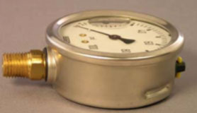
Most of the time, the answer depends on geography. In the U.S. or Canada, the pressure gauge will most likely come with an NPT (National Pipe Tapered) connection. This thread type, standardized by ANSI (American National Standards Institute) and ASME (American Society of Mechanical Engineers), is typical among North American measuring instruments, found in piping systems, pumps, compressors, plumbing systems, mobile working machines, and many more applications.

Male (external) NPT connections are somewhat conical, with the diameter of the threads decreasing slightly from socket to tip. Tapered threads seal along the flanks of the thread. Due to the spiral leak path, however, Teflon® tape (PTFE) or a sealing compound is required to create a good seal. The most common sizes for pressure gauge connections in the U.S. are ⅛-inch NPT, ¼-inch NPT, and ½-inch NPT.

The U.S. and Canada also use parallel threads like the NPSM (National Pipe Straight Mechanical) connector. However, this thread type is typically found as a female (internal) component in non-pressurized devices like thermowells.

The tapered shape of the NPT threads allows users to continue turning the connection several more degrees after making the seal, until the instrument reaches the desired position. Tightening, though, has to be done with care: Too much compression can lead to galling, and over-tightening can damage the threads. These situations are problematic in applications that require regular installation and removal of the pressure gauge.


G Connections in Pressure Gauges

WIKA G 1/4-inch B Connection
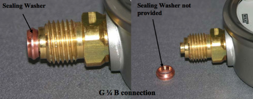
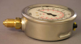
If the pipe assembly is in Europe, Asia, or Latin America – basically anywhere else in the world but the U.S. and Canada – the pressure gauge will very likely have the straight threads of a British Standard Pipe Parallel (BSPP) connector, denoted by the letter G*. The tapered variants from the BSP classification system are denoted by ISO7, for example, R1/4-ISO7.

They are often referred to as metric connections because they are used in the metric system, and the dimensions are based on metric measurements. G connections have a straight body (constant diameter) with parallel (straight) threads. The main purpose of the parallel threads is to contain the pressure, which allows for regular installations and removals without damaging the thread. A sealing washer is required to seal the connection. As sealing of the connection takes place on the washer and not on the thread itself, no sealing compound or PTFE tape is required.

WIKA Sealing washer on a pressure gauge with a G Connection


Since the thread of a G connection will bottom out at the wrench flat, no threads are left exposed. Once the connector bottoms out to make the seal, the positioning of the instrument cannot be changed. To avoid the problem of awkward gauge positioning, use a “crush washer” and hand-tighten the connection. At the resistance point, approximately 1½ turns are left before the crush washer flattens out. This leeway allows the user to fine-tune the pressure gauge’s final position with a wrench**. If the position of the instrument is not critical, a flat washer can be used instead.

Eyeballing the Difference Between NPT and G Connections

When placed side by side, the difference between the two connection types is clear. The NPT thread is slightly tapered, while the G connection is straight. Another obvious visual: The G connector ends with a small protrusion (nipple), used to center the gasket. If calipers are handy, a third method is to measure the angle between threads: NPT threads are 60°, while BSP threads are 55°.

But how about when the pressure gauge is already inserted into the process? Is there an easy way to tell which connector type an instrument has without removing it? Yes. Because a G connection bottoms out, no threads are visible. In an NPT connection, a few threads or exposed PTFE tape can be seen.
 

NPT vs. G Connections

 NPT ConnectionsG Connections
Thread ShapeSlightly aperedStraight
Tip of threadBluntSmall protrusion (nipple)
Thread angle60°55°
Visual when assembledVisible thread or PTFE tapeNo exposed thread

Talk to one of our experts today at (855) 737-4714, or fill out our online form to learn more.