First in a series of four articles
In high-precision motion control, system performance is often judged simply by the specifications of the mechanics alone. The actuators are typically sorted by a standard set of specifications such as repeatability, accuracy, and load capability. For many applications, this is all that’s required. Others will need an understanding of those specifications to make sure the basic assumptions for them are met during installation. Achieving true precision, however, requires a deeper understanding of the full motion control system from the mechanics to the motors, drives, and controls.
This is the first in a series of articles that will explore how each layer of technology contributes to the overall systems performance. First, we look at the mechanics, examining critical factors that are often overlooked: bearing deflection, body stiffness, and structural smoothness. In the second part of the series, we’ll discuss how motor design and construction can cause torque ripple which affects everything else. Next, the discussion will surround the importance of the designs and features of drives and controls for the system, and finally, we’ll end with the critical elements of the system integration itself.
In all cases, there are details that do not show up on data sheets but can make or break the high-performance expectations of the entire system. As motion systems push beyond micron-level accuracy, traditional specifications start to lose their typical meaning and relevance, making nuanced engineering decisions essential. This series aims to help engineers, designers and system integrators recognize just how important each decision is in putting a high-precision motion system together.
What level of performance are you designing for?
There are three general tiers of performance to consider in a motion control system; basic, specification-level, and pushing-beyond-the-specifications performance.
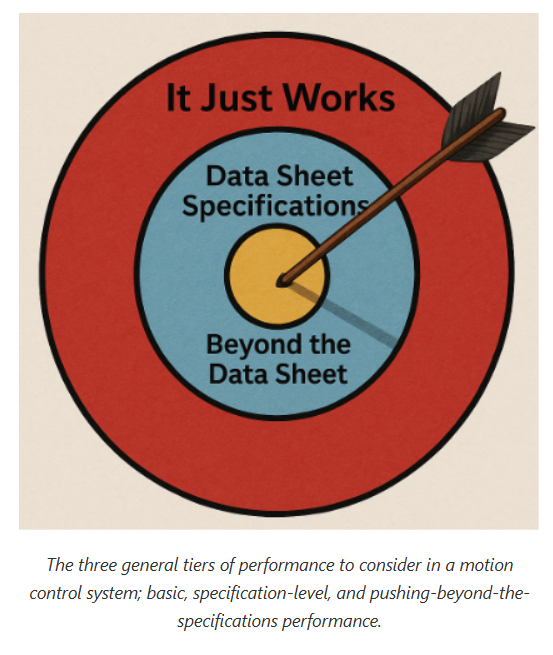
In the level requiring just basic functionality, there is minimal concern about the specifications and integration of the products, because whatever they do will be good enough. Sometimes applications just require an actuator to move something. In these cases, it’s understood that something will work just by throwing it in there. Other times, it is obvious that the actuator advertising 20-micron repeatability is quite good enough for the application where 100 microns of repeatability is all that is needed.
Many applications need the specified performance in the data sheets. These specifications, however, are derived with certain assumptions — a certain life span, a particular location of the load, a given temperature, and even how it is mounted. If these assumptions are not met upon installation and during the application, then the product won’t hit the expected specifications.
Then there are the applications that require performance beyond the data sheet’s specifications. These are often complex high-performing systems that need to be well understood but are also an opportunity for the designers to understand the data sheet’s specifications and what they actually mean as rules, and what are just guidelines (to quote a famous pirate).
Mechanics: The foundation of performance
For many applications, simply choosing an actuator from the catalog with performance well above what’s required works perfectly fine. The requirement may be an accuracy of 100 microns so selecting an actuator with a specification of 10 microns will work even if it is mounted to a wavy surface in a dirty environment. This is great for quick prototypes, proof-of-concepts, and applications where the performance isn’t critical.
Some applications need the performance of the actuator specified in the datasheet. In these cases, special attention must be paid to the mounting requirements, the location of the load, and the expected lifespan in comparison to the listed assumptions for that actuator’s stated performance.
For the most demanding applications, things become complex quickly. For example, if an engineer wants an XY system with the Y-actuator stacked on top of the X and the load cantilevered off to the side of the X, what is the repeatability of the load? Can you take the repeatability of the Y and add it to the X so that 10 microns for the Y plus 10 microns for the X gives a 20-micron repeatability? Well, that doesn’t work because those directions are orthogonal to each other.
So then, what if we take the geometric resultant of them using the classic A2 + B2 = C2 equation?
That means that the diagonal C = SQRT (102 + 102) which gives us a repeatability of just over 14 microns. That’s great if the vertical element of the load’s location is irrelevant. The assumption of the actuator’s repeatability is usually that the load is located directly over the carriage where bearing deflection caused by the cantilevered load isn’t considered. A Y-actuator causing a cantilevered load on the X-axis is going to cause bearing deflection which may be an issue if not accounted for nor expected. In extreme cases there can even be body and base deflection to consider.
Sticking with that same scenario but in a more extreme and demanding application, vibration and stability become factors as well. Having a load bouncing around uncontrollably at the end of an arm is adverse to most applications at this level of performance. The typical solution is to support the cantilever load with an outrigger bearing or a follower X-axis of some kind, all of which introduce their own variables that need to be considered. Is the Y-axis with its supporting brackets stiff enough to firmly support the load? Is it stiff enough to keep the X and X′ aligned? Or should there be a drive shaft between the X and X′? Or perhaps motors on both of the X and X′?
One high-precision solution is to put air-bearings on granite under the cantilevered load. However, the minimal friction of air bearings can present an unforeseen difficulty in tuning the system. One application required reducing the air pressure to induce friction just so the motion of the load on XY linear motors would actually settle into position. In that application, settling within one second was acceptable because the resulting precision was the most important requirement. Other applications will require much faster settling times. Knowing what is most important about the application will dictate which design option to pursue.
Each of these design decisions affects the options available for the drives and controls. Some decisions require the controls to be more sophisticated than others. For example, a gantry with motorized X and X′ axes will require another drive plus controls that can synchronize the two in some fashion. There are factors to be considered there as well, which will be discussed in future articles in this series. Some electronics may be able to control the motion but won’t be up to the task of hitting the desired goal the mechanics were designed for.
High-precision applications require a holistic approach to the entire system from the mechanics to the electronics to the integration by a knowledgeable design team who understands the goal of the application and the ramifications of all of their design decisions. This is why sharing the goal of the application with the product experts is important and not isolating them with specification requirements.
Article featured in Design World Magazine
Be sure to check out the entire series:
Part 1: The Many Layers of Performance and Specifications in Motion Control - Mechanics
Part 2: The Many Layers of Performance and Specifications in Motion Control – Motors
Part 3: The Many Layers of Performance and Specifications in Motion Control – Drives and Controls
Part 4: The Many Layers of Performance and Specifications in Motion Control – Critical Elements of System Integration