Actuator Selection Pitfalls: How Environment Trumps Basic Specs

At first glance, selecting the right actuator for your application might seem straightforward. You figure out the load, define the motion, and move forward. For a large portion of applications, that approach works just fine. However, once you step outside that standard 80 percent, things can get complicated quickly.
Different industries bring very different expectations. What works perfectly in a factory setting might fail in a cleanroom, for example. That is why actuator selection often becomes less about basic specs and more about understanding the environment it needs to operate in.
Materials are a great example. In aerospace, weight is critical because lighter components improve efficiency. If that same actuator is used in space, additional concerns come into play. In food and beverage applications, priorities shift toward corrosion resistance, heat tolerance, and easy cleaning. In semiconductor manufacturing, cleanliness is essential since even tiny particles can damage wafers.
Temperature is one of the first factors to consider. The wrong lubricant in a high-heat setting can break down and increase wear, shortening the actuator’s lifespan. In very cold environments, lubricants can thicken, and materials can become brittle, reducing performance. Temperature changes can also impact precision, which matters in high-accuracy systems.
Cleanroom environments add another layer of complexity. Any moving component produces some level of particulate. In certain industries, even microscopic contamination is unacceptable. To reduce this risk, manufacturers may use heavier lubricants or remove materials like polymers from wear surfaces. The stricter the cleanroom classification, the tighter the limits on allowable particles.
Pressure is another key consideration. In vacuum environments, some materials can outgas, which may damage both the actuator and the surrounding process. Cooling can also become an issue because there is less air to carry heat away. In high-pressure settings, additional concerns such as sealing, corrosion resistance, and structural integrity come into play.
Corrosive environments are another common challenge. Stainless steel is often used in place of carbon steel to improve durability. Designs are typically simplified to eliminate crevices where moisture or chemicals could collect. In hygienic applications, this is not just about protecting equipment but also about preventing contamination and supporting effective cleaning processes.
In explosion-prone environments such as oil and gas operations, safety becomes the primary focus. Electrical charge buildup can create a risk of ignition, so proper grounding and bonding are essential. Components may also require protective coatings or encapsulation to prevent sparks.
After all these factors are considered, the conversation usually turns to price versus performance. Everyone wants the best performance at the lowest cost, but trade-offs are inevitable. Not all manufacturers rate their products the same way, and performance claims can vary. An actuator used occasionally will have very different requirements than one running continuously for years. If failure could create safety risks, higher performance and reliability are non-negotiable.
Choosing the right actuator is not just a technical decision. It requires a clear understanding of the environment, the risks, and the expected lifespan. Taking the time to evaluate these factors, and consulting experienced professionals when needed, can help avoid costly mistakes.
I had an article published in Design World Magazine that went into more detail about each one of these environments. Give it a read if you’re looking for a more in-depth discussion.
Talk to one of our experts today at (855) 737-4716 or fill out our online form to learn more.
Stop Overpaying for Level Measurement - A 3-Factor Selection Guide
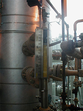
Accurate level measurement is a critical element for many applications in the industrial world; without it, most processes simply cannot function properly. While most plant operators understand this truth, general knowledge often falls short once the conversation shifts to level transmitter selection and the best way to achieve that accuracy.
Achieving accurate level measurement is not a one-size-fits-all approach. There are several different approaches you can take. However, they are not all optimal depending on the circumstances. This is especially true when cost is introduced to the decision-making process. The bottom line is you don’t want to have to pay for something that isn’t necessary. Some applications require expensive level measurement technology while others can be perfectly serviced with something less robust.
How do we know what our particular application requires? There are three factors to consider before making the decision: Type, Vessel Design and Process Variation
 Type is something that sounds broad on the surface, but essentially, we need to understand the nature of the process. Is it a continues process? Does it have an on/off capability associated with it? Is it a batch/recipe control application? If so, the accuracy required is going to be fairly high. We want to know what kind of output is needed. For example, does it require an analog 4-20mA, Modbus or Ethernet? Do we need a visual indication or verification function?
Once we have a pretty good handle on the type of application, we need to discuss the vessel. The type of vessel associated with the application will have an influence on the technology required. Tanks come in different forms and have features that vary from design to design. Is it above or below grade? Is it a floating roof storage tank? Is it a bullet or spherical pressurized tank? What is the material? Where is the instrument entry point?
Finally, what is the process variation to consider. Is the vessel pressurized? What is the temperature range? Etc.
Only once you have determined all of the factors of a particular process are you ready to make decisions concerning the level transmitter technology that works best for you.
The technology comes in two basic forms: differential and submersible. Differential technology can be used on pressurized above grade vessels and requires stable density. It is ideal for dirty or viscous processes.
Submersible technology involves a wetted sensor, requiring a small entry port at the top of the vessel or below grade sump, reservoir or lake, suspended by an electrical cable to the bottom.
There is also conductivity, guided-wave radar, ultrasonic, radar and magnetostrictive technologies available for particular applications. The key is not to make any decisions without discussing it with an expert who can guide you in the most ideal direction based on your particular circumstances. I had an article published in Process Instrumentation magazine last year where I went through this decision tree very thoroughly. Check it out if you haven’t already.
Why O-Ring Design Matters
- Read more about Why O-Ring Design Matters
- Log in or register to post comments
Rapid Response Secures Critical Filtration Supply
When a leading semiconductor manufacturer faced an urgent filtration supply challenge, Valin responded with speed, flexibility, and a solution-oriented approach. What began as a time-sensitive request quickly evolved into a long-term supply relationship, demonstrating Valin’s ability to deliver under pressure and create lasting value.
The Challenge
An engineer at a major semiconductor facility urgently needed a specific type of filter to support ongoing operations. Immediate availability was critical, and any delay risked disrupting production. The requested product was not typically stocked, creating a potential supply gap at a crucial moment.
The Solution
Valin quickly assessed available options and identified an equivalent filter in stock at another facility. Without delay, the team:
- Provided product specifications and documentation to validate the alternative
- Delivered competitive pricing for rapid approval
- Offered a qualified cross-reference solution that met the application requirements
Once the alternative was approved, Valin took an additional proactive step, initiating transfer of the filters to a local warehouse before receiving the formal purchase order. This ensured zero delay in fulfillment and demonstrated a strong commitment to the customer’s operational continuity.
The Result
Valin ensured seamless delivery by personally expediting the final handoff to the customer site. The impact was immediate:
- Critical operations continued without interruption
- The customer gained confidence in a reliable alternative supply source
- Valin successfully displaced the incumbent product
The responsiveness and execution left a lasting impression. The customer quickly followed up with a significantly larger order, establishing an ongoing supply relationship.
Conclusion
This case highlights Valin’s ability to act decisively when customers need it most. By combining technical expertise, supply chain agility, and a customer-first mindset, Valin not only solved an urgent problem, but also built the foundation for a long-term partnership.
UL 508A Pneumatic Control Panels for Water Systems
In a past article we shared how Valin Corporation partnered with a California sanitary water district to tackle a growing reliability issue.
After more than a decade of service, the district’s pneumatic valve manifolds were beginning to show clear signs of wear. Leaks, pressure drops, and inconsistent flow were starting to impact valve performance and timing. If left unaddressed, these could lead to broader system inefficiencies or even damage.
The team knew it was time for a smarter, more dependable solution. They also needed something that wouldn’t create new headaches during installation or operation.
That’s where Valin came in.
Rather than simply replacing components, Valin delivered a fully integrated solution centered around UL 508A-certified pneumatic control panels. These panels were designed not just to restore performance, but to improve it. They’re designed to help regulate airflow, manage pressure, and support critical systems.
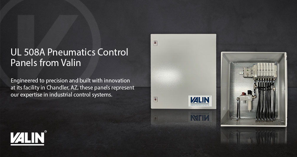
But in water and wastewater environments, performance is only half the battle. Moisture poses a constant threat to pneumatic systems. Even small amounts can compromise valve functionality. To address this, the solution incorporated a specialized filter regulator to ensure only clean, dry air reached the system. This proactive step helps prevent failures before they start, extending equipment life and reducing maintenance demands.
One of the district’s biggest concerns was implementation. Control panels can be complex, and not every team has the resources or expertise to manage programming and integration from scratch. Valin eliminated that friction by delivering a turnkey, pre-assembled package. Everything was engineered to work together seamlessly right out of the box.
The result? A smooth transition, improved reliability, and a solution built to withstand the demands of a challenging environment. In fact, the district was so satisfied with the first deployment that they’ve already signaled their intent to continue working with Valin as a preferred partner moving forward.
For the full breakdown and technical details, check out the article we had published in Processing Magazine.