
Resources
Stop Cavitation from Destroying Your Control Valve Trims
Submitted by Dr. Jon F. Monsen and Dr. Hans D. Baumann
The devastating effects cavitation can have on control valve internals is widely appreciated. In this article, the authors therefore explain the origins of cavitation, provide an easy-to-use method to estimate cavitation sound levels and conclude with approaches to reduce or even avoid cavitation.
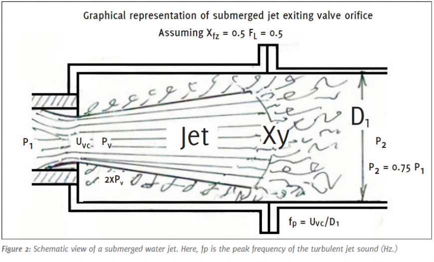
 It has been observed that when the downstream pressure in a valve decreases at and beyond a corresponding pressure ratio, called Xfz (see Ref. 1), the static pressure in the valve’s orifice reaches the vapor pressure of the liquid, this causes evaporation of some of the liquid with simultaneous formation of small vapor bubbles. At this point the liquid reaches its highest velocity. After passing the orifice, the liquid velocity starts to decrease while the static pressure increases. When the liquid static pressure exceeds vapor pressure, the bubbles start to implode causing sonic shock waves. This causes acoustic sound waves following the laws of gas acoustics.
Following further reduction in outlet pressure causes more of the diameter of the jet to enlarge and its velocity to decrease in proportion to the increased static pressure following the laws of Bernoulli (assuming constant inlet pressure).
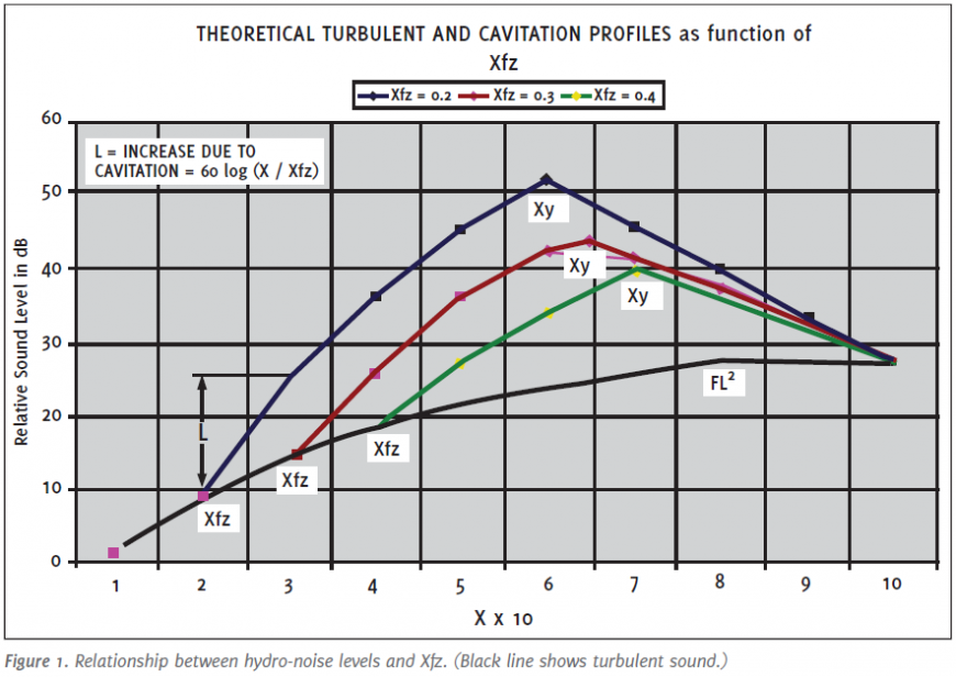
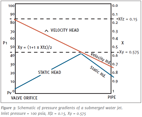
 The resultant sound pressure from cavitation increases corresponding to 60 log(X/Xfz) following the acoustic gas laws (here X is a pressure ratio = (P1 - P2)/(P1 - Pv)). Xfz is a coefficient of incipient cavitation. Figure 1 shows the relationship between Xfz, the coefficient of incipient cavitation and the resultant sound level. Manufacturers publish specific Xfz values for their valves. Xy signifies the maximum cavitation amplitude. It is defined as Xy = (1+Xfz)/2. According to Bernoulli’s law, in a horizontal pipe (or valve housing), any increase in the speed of the fluid occurs simultaneously with a decrease in static pressure without a change in the fluid’s potential energy. Of course this also works in reverse, that is, static pressure will increase when the speed decreases. Here is the chain of events: (P1 - P2)→ X →Jet velocity← static pressure. Finally, at a pressure ratio Xy, about half way between Xfz and X = 1, the cavitation process reverses. Here, the static pressure matches the dynamic pressure, or velocity head (see Figure 3).
 Of significance is that at this pressure ratio, the resultant downstream pressure is approximately one half of that of the downstream pressure at Xfz. Following Xy, further outlet pressure reduction results in the termination of bubble implosions followed by a rapid but somewhat disorganized decrease in sound pressure, until the cavitation sound pressure level reaches that of the turbulent water. This happens at, or close to, X = 1, followed by a process of flashing. At this stage all vapor bubbles which escaped implosions stay dispersed in the turbulent water.
Little kinetic energy (except some friction loss and acoustic power conversion) is converted during the jet’s expansion, However following the Xy pressure ratio nearly all of the kinetic energy (equivalent to P1 – P2) is converted into heat due to turbulence.
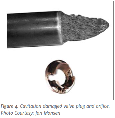
As Figure 4 shows, prolonged cavitation has eaten away one half of the original parabolic valve plug. Similar destruction has happened at the corresponding valve orifice. It should be noted that liquids other than water can be just as destructive. Consider oil in pipelines for example. There is a correlation between sound and erosion. Destructions like these happen when the external sound level exceeds 80 dB(A); also Jon Monsen (Ref. 2) suggests a sliding scale such as 85 dB(A) for valve sizes 4” to 6”, 90 dB(A) for sizes 8” to 14” and 95 dB(A) for even larger sizes. There is no known valve trim material which could withstand cavitation damage due to the extremely high pressure waves (exceeding 100,000 psi) of the imploding vapor bubbles, even though, hardened trim such as ceramics or Stellite® have shown to prolong service life.
Estimating the Sound Level of Cavitation
Here is a simplified, but accurate, method which can be performed using a simple device such as a pocket calculator.
Input Needed:
Pipe diameter downstream of valve D in inch (D = d/25.4 if d in mm), P1 in psia (bara x14.5), P2 in psia (bara x14.5), flow coefficient Cv (at operating conditions), pressure recovery coefficient without expander FL, coefficient of incipient cavitation Xfz, liquid vapor pressure Pv, valve type modifier rw (3 for globe valves ).
Initial Calculations:
Pressure ratio X = (P1 – P2)/(P1- Pv). Xy = X at max. cavitation = (1.00+Xfz)/2.
Calculation Steps:
A = 8 log(D) +12log(Cv/D2) +4 in dB
B = 35 log(P1) – 35 for US, or 35 log(14.5 p) - 35 if p is in bara.
c1 = 30 log(10X) X maximum = FL2.
This equation gives turbulent sound level in dB(A) at 1m.
c2 if X is larger than Xfz but below Xy then c2 = 60 log(X/Xfz). if X is above Xy then c2 = 60 log(Xy/Xfz); otherwise use zero. This defines increasing cavitation sound level in dB
c3 if X is larger than Xy then c3 = 120 log(X/Xy); otherwise use zero. This denotes decreasing cavitation sound level in dB.
C = c1 +c2 - c3 in dB(A). Final external sound level LpAe1m = A + B + C - rw plus modifiers, in dB(A) at 1 m.
Following further reduction in outlet pressure causes more of the diameter of the jet to enlarge and its velocity to decrease in proportion to the increased static pressure following the laws of Bernoulli (assuming constant inlet pressure).
Little kinetic energy (except some friction loss and acoustic power conversion) is converted during the jet’s expansion, However following the Xy pressure ratio nearly all of the kinetic energy (equivalent to P1 – P2) is converted into heat due to turbulence.
Damage Caused by Cavitation
Estimating the Sound Level of Cavitation
Here is a simplified, but accurate, method which can be performed using a simple device such as a pocket calculator.
Input Needed:
Pipe diameter downstream of valve D in inch (D = d/25.4 if d in mm), P1 in psia (bara x14.5), P2 in psia (bara x14.5), flow coefficient Cv (at operating conditions), pressure recovery coefficient without expander FL, coefficient of incipient cavitation Xfz, liquid vapor pressure Pv, valve type modifier rw (3 for globe valves ).
Initial Calculations:
Pressure ratio X = (P1 – P2)/(P1- Pv). Xy = X at max. cavitation = (1.00+Xfz)/2.
Calculation Steps:
A = 8 log(D) +12log(Cv/D2) +4 in dB
B = 35 log(P1) – 35 for US, or 35 log(14.5 p) - 35 if p is in bara.
c1 = 30 log(10X) X maximum = FL2.
This equation gives turbulent sound level in dB(A) at 1m.
c2 if X is larger than Xfz but below Xy then c2 = 60 log(X/Xfz). if X is above Xy then c2 = 60 log(Xy/Xfz); otherwise use zero. This defines increasing cavitation sound level in dB
c3 if X is larger than Xy then c3 = 120 log(X/Xy); otherwise use zero. This denotes decreasing cavitation sound level in dB.
C = c1 +c2 - c3 in dB(A). Final external sound level LpAe1m = A + B + C - rw plus modifiers, in dB(A) at 1 m.
Modifiers: For pipe schedule: Schedule
40=0, schedule 80=-4 dB.
Worked example
A 3” butterfly valve installed in a 6” pipe,
P1=100 psia, P2=40 psia, Pv=0.5 psia,
Cv under actual flow = 85. Xfz given as
0.28. X=(P1 – P2)/P1 – Pv)=0.6 FL=0.7.
Note, X is limited to FL2
A=8log(6) + 12log(85/36) + 4=14.7 dB(A)
B=35log(100) – 35=35 dB(A)
c1=30log(10 x FL2)=20.7 dB(A)
c2=60log(0.6/0.28)=19.9
c3=0
Total sound level=A + B + c1 + c2=90.3 dB(A).
at 1 meter from a schedule 40 pipe.
How to Avoid or Reduce Cavitation
The first line of the defense is to select valve types for your applications, which have a high Xfz factor. As you can see from Figure 1, the difference between an Xfz (incipient coefficient of cavitation) of 0.2 and one of 0.4 is an extra sound level of 14 dB. If this cannot be done, specify an “anti-cavitation” valve trim.
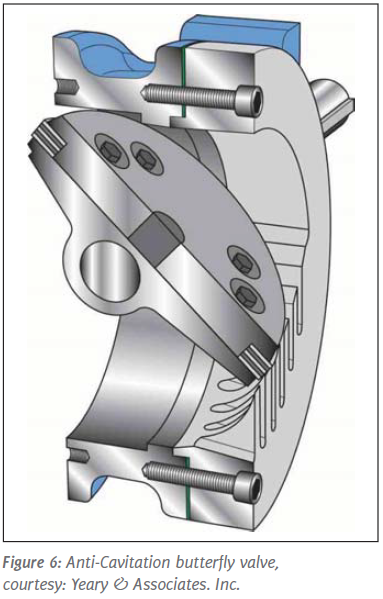
These devices consist typically of multi-ported cages or valve plugs, although special butterfly valves having serrated or slotted vanes also are effective. Similarly effective are ball valves having parts of a ball slotted or multi-ported.
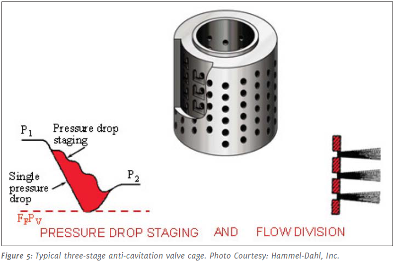
Single stage multi-ported devices are only indirectly effective by increasing the Xfz factor of the valve. More effective are multi-stage devices such as the valve cage pictured in Figure 5, since they split up the overall pressure drop across the valve in addition to increasing the Xfz factor. Attention must be paid to ensure that the Xfz factor of the last stage is high enough; otherwise the inner valve plug will be damaged.
These devices consist typically of multi-ported cages or valve plugs, although special butterfly valves having serrated or slotted vanes also are effective. Similarly effective are ball valves having parts of a ball slotted or multi-ported.
Single stage multi-ported devices are only indirectly effective by increasing the Xfz factor of the valve. More effective are multi-stage devices such as the valve cage pictured in Figure 5, since they split up the overall pressure drop across the valve in addition to increasing the Xfz factor. Attention must be paid to ensure that the Xfz factor of the last stage is high enough; otherwise the inner valve plug will be damaged.
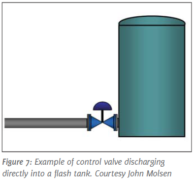
For let-down valves, such as pressure reduction from a well, emptying a tank, or back-pressure from a cooling tower, the best solution is to use conventional valves and let a valve absorb the whole pressure drop in one stage. This makes X equal, or close to one. As you can see from the Figure 1, here the only sound level (and absence of cavitation) is from turbulence (the lower black line). However, this works only if there is no downstream pipe. This means that the valve has to be attached directly to a tank (Figure 7) or sump of a pump. Otherwise the fluid should be discharged to atmosphere, so for example to a settling pond. The reason is that downstream pipes build-up back-pressure due to the high volume generated by the high content of un-imploded vapor bubbles. Even though the vapor content might only be 2%, the ratio between vapor and water specific volume is above 1000:1. As a result, the vapor has to be compressed in order to pass through the pipe. The resultant back pressure, in turn, creates a secondary cavitation (now X is below 1) which typically is responsible for corroded pipes and elbows (erroneously attributed to “flashing”). Another tried approach is to install two identical valves in series. This is only marginal effective since the combined FL or Xfz is only increased by 40% instead of being doubled [Xfz total = (2x Xfz)0.5].
Multi-ported resistance plates also are employed in order to split the pressure drop (keeping the valve’s pressure drop below Xfz while the rest is absorbed by the plate). However this works only at fairly high flow rates since the pressure drop through the plate decreases rapidly by the square root of the flow rates.
Noise reduction for up to 10 dB has been achieved by injecting air into the cavitating liquid. Here the injected air bubbles absorb some of the impact of the cavitating vapor bubbles. Finally, pay attention to piping locations. Elevated inlet pipes increase inlet pressure and pressure drop, and lower pointing outlet piping increases suction and lowers outlet pressure. This could result in flashing if the outlet pressure is close to the vapor pressure.
Click on the link below to read the full article featured in Valve World Magazine.
References
Ref 1: IEC Standard 60534-8-4, Prediction of Noise from Hydraulic Fluids, International Electronical Commission, Geneva, Switzerland.
Ref 2: Jon Monsen, Predicting Cavitation Damage in Control Valves, Flow Control Magazine, May, 2018, P. 14-17.
Ref 3: Hans D. Baumann, How Loud is my Control Valve? VALVE-WORLD Magazine, May, 2018, P.1-2.
Ref 4: Hans D. Baumann, Fluid Mechanics of Control Valves, ISA Publication, 2019.
About the Authors
Jon F. Monsen, Ph.D., P.E., is a control valve technology consultant at Valin Corporation, with more than 40 years’ experience in the control valve industry. He has lectured nationally and internationally on the subjects of control valve application and sizing, and is the author of the chapter on “Computerized Control Valve Sizing” in the ISA Practical Guides book on
Control Valves. He is also the author of the book Control Valve Application Technology: Techniques and Considerations for Properly Selecting the Right Control Valve.
Dr. Baumann, a former VP of Masoneilan and Fisher Controls is now an international consultant. He is credited with over 100 US patents and has authored 140 publications and seven books, including the Control Valve Primer now in the fourth edition. Dr. Baumann is an Honorary Member of ISA and a Fellow Member of ASME.

Multi-ported resistance plates also are employed in order to split the pressure drop (keeping the valve’s pressure drop below Xfz while the rest is absorbed by the plate). However this works only at fairly high flow rates since the pressure drop through the plate decreases rapidly by the square root of the flow rates.
Noise reduction for up to 10 dB has been achieved by injecting air into the cavitating liquid. Here the injected air bubbles absorb some of the impact of the cavitating vapor bubbles. Finally, pay attention to piping locations. Elevated inlet pipes increase inlet pressure and pressure drop, and lower pointing outlet piping increases suction and lowers outlet pressure. This could result in flashing if the outlet pressure is close to the vapor pressure.
Click on the link below to read the full article featured in Valve World Magazine.
Stop Cavitation from Destroying Your Control Valve Trims
References
Ref 1: IEC Standard 60534-8-4, Prediction of Noise from Hydraulic Fluids, International Electronical Commission, Geneva, Switzerland.
Ref 2: Jon Monsen, Predicting Cavitation Damage in Control Valves, Flow Control Magazine, May, 2018, P. 14-17.
Ref 3: Hans D. Baumann, How Loud is my Control Valve? VALVE-WORLD Magazine, May, 2018, P.1-2.
Ref 4: Hans D. Baumann, Fluid Mechanics of Control Valves, ISA Publication, 2019.
About the Authors
Jon F. Monsen, Ph.D., P.E., is a control valve technology consultant at Valin Corporation, with more than 40 years’ experience in the control valve industry. He has lectured nationally and internationally on the subjects of control valve application and sizing, and is the author of the chapter on “Computerized Control Valve Sizing” in the ISA Practical Guides book on
Control Valves. He is also the author of the book Control Valve Application Technology: Techniques and Considerations for Properly Selecting the Right Control Valve.
Dr. Baumann, a former VP of Masoneilan and Fisher Controls is now an international consultant. He is credited with over 100 US patents and has authored 140 publications and seven books, including the Control Valve Primer now in the fourth edition. Dr. Baumann is an Honorary Member of ISA and a Fellow Member of ASME.
A lesson for me is that I need to involve you earlier in the program.
You were tireless in your support and it will not be forgotten!
Latest from Valin's Blog
The NIST Chemistry WebBook contains a great deal of information regarding the properties of a broad range of chemicals and is helpful for those who deal with chemical processes.In this article, Jon Monsen has outlined the procedure for finding the actual density of a gas using the WebBook.